|


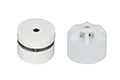
CP-5110
Sentek
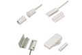
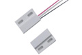
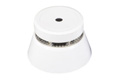
The CP-5110 manual call-point is installed in public places, such as the wall of the building walkway,near the hotel information desk and other eye-catching places. After you confirming the fire, press the button to send a fire alarm signal to the controller. The CP-5110 manual call-point adopts a large plastic structure and it is consisting of two parts: the mounting base and top cover. The installation and disassembly of the CP-5110 manual call-point are simple and easy,which is convenient for engineering debugging and maintenance. After pressing the button, you need to reset it with a dedicated key, just inset the key into the keyhole and push it.
This product is not suitable for use in the following locations:
(1) There is a large oil mist and corrosive gases pollution.
(2) The relative humidity is greater than 95%.

DC24V Power Supply | R2(-) (470R) | R1(-) (680R) |
LED (+) | 44+2mA | 30+2mA |
C (+) | 51+2mA | 35+2mA |
Working Voltage | DC3V-DC33V | |
In the normal working status, the indicator of the product is off. When there is a fire, press the button in the middle of the product and the two alarm indicators will be on, (If the anode is connected to the LED, the cathode is connected to R1 , the indicator will be on and there will generate a 30±2mA alarm current on the line L1 and L2. If the anode is connected to the LED,the cathode is connected to R2 , the indicator will be on and there will generate a 44±2mA alarm current on the line L1 and L2. If the anode is connected to the C, the cathode is connected to R1 , the indicator will be off and there will generate a 35±2mA alarm current on the line L1 and L2.If the anode is connected to the C, the cathode is connected to R2 , the indicator will be off and there will generate a 51±2mA alarm current on the line L1 and L2.)The controller will recognize the alarm through the current change and send an alarm signal. To exit the alarm, you need to reset it with a dedicated key provided
by the company.Environment: Temperature -10℃~+55℃, Relative humidity ≤95% RH (40℃±2℃), indoor. Executive standard: EN 54-11.


ConnectionMethod | Z1 | Z2 | S1 | S2 | T1 | T2 |
R1 | IN(+) | OUT(+) | (-) | |||
R2 | IN(+) | OUT(+) | (-) | |||
LED+ R1 | IN(+) | OUT(+) | (-) | (-) | ||
LED+ R2 | IN(+) | OUT(+) |
It is recommended to use RVS-2×1.0mm² twisted multi-strand copper core wire to lay through the metal or flame
retardant tube. The actual working voltage of the manual call-point at the farthest end of the connection is
guaranteed to be more than 10V. Otherwise, the wire diameter of the wire should be increased.
Insert a slotted screwdriver into the slot of the card and push it down firmly so that the buckle on the upper cover is disengaged from the slot on thebase, and then pull the slotted screwdriver to the right to disengage the upper cover from the base slot. Then, in the same way, the other buckle on thesame side is separated from the base card slot. After that, grasping the upper cover and pullingit to one side, the upper cover can be separatedfrom the base. During the disassembly, be careful not to damage the buckle and the card slot.

At least one manual call-point should be set for each fire zone, and the any position within the partition to the manual call-point should not exceed 30 meters. The specific parameters should be reference to "Code for Design of Automatic Fire Alarm System" (GB 50116-2013).The installation of the manual call-point should refer to the standard drawing "Fire Alarm and Fire Control" 04X501. Manual call-points are installed on walls that are perpendicular to the ground or other partitions that are perpendicular to the ground.
Maintenance should be done by a professional company (preferably the Manufacturer).